Common Troubleshooting Strategies and Techniques
The following article is based on years of experience.Being a good computer technician is based on experience but also in reading and research. I Challenge veryone not only PC technician can fix computer problems but you also can fix this problem just keep reading and keep searching from the internet Directron.com is one of the site how to fix computer problems. It is provided as a free service customers and visitor . Ho you are welcome to distribute these computer support tips free to your friends and associates as long as it’s not for commercial purposes and you acknowledge the source. . All of us will start from basic here are the basic troubleshooting techniques and Strategies in troubleshooting minor computer problems.
Here are five common-sense techniques and strategies to solve common computer hardware problems.
(1) Trial-and-error
Personal computers are highly modular by design. The most powerful trouble-shooting technique is to isolate the problem to a specific component by trial-and-error. Swap compatible components and see if the system still works. Try different peripherals on different machines and see if the same problem occurs. Make one change at a time.
(2) "It’s the cable, s—–."
More than 70% of all computer problems are related to cabling and connections. Ensure all cables are connected firmly. IDE and floppy ribbon cables and power cables can often go loose. Ensure microprocessor, memory modules, and adapters such as video card and sound card are inserted correctly and didn’t "pop-up" during transportation.
(3) Don’t be frustrated!
Don’t be afraid of computer problems. It is often the best opportunity to learn. Trouble-shooting is part of the fun of owning a computer. Imagine the satisfaction you could get by solving a problem yourself.
Of course the fun could ran out quickly once you are frustrated and have spent too much time on the same problem. If you feel frustrated, it’s time to leave it for a while and go back with some new ideas or call someone who can help. Rule of thumb: You shouldn’t spend more than three hours on the same problem at one time.
(4) Take notes!
Take notes of what you have done and all the error messages. You may need to use them later. For instance, when you see an unusual blue screen with an error message, copy the entire message onto a piece of paper. In many situations, that message may point to the right direction in getting the problem solved quickly.
(5) Take a look?
It’s OK to open a computer case and take a look inside. There is only 5V and 12V DC voltage supplied to the components outside the power supply. Those who have never seen the inside
Share and Enjoy:

"Computer Repair.Networking. Computer Hardware/software.CCTV Installation.Research.Encoding.Offline/Online Gaming.E-mail.Scanning.Remixing. CD Burn.DVD Movies.Xerox.PSP Games.Mp3/Mp4 Downloading.etc. "WE DO WHAT WE CAN" CALL or TEXT: 0926-186-8050
how to remove autorun.inf
Computer Virus attacks!
There’s a strain of computer virus that infects the file server and workstations of the computer laboratory of Hercor College, Roxas City, Capiz, Philippines. It hides itself by using the name ctfmon.exe (Ctfmon.exe monitors the active windows and provides text input service support for speech recognition, handwriting recognition, keyboard, translation, and other alternative user input technologies.) It was detected by TrendMicro 2007 as PE_VBAC.A virus and as MianCrypt.Gen virus by AVAST.
The said virus hides itself inside a folder named Recycled. The folder has a hidden/system/read-only attribute, that’s why you can’t see it if you will use the Search window. When your system is infected by the said virus, it infects every drive connected to your PC by dropping VCAB.DLL to the internet temporary folder and creating the CTFMON.EXE to folder Recyled & AUTORUN.INF to the root directory of every drive. That’s why when you connect your USB sticks to the infected PC it will be infected immediately, the USB disks will be the new carrier for the virus. The program runs every time you start your computer because it copy itself in the Startup folder of the Start Menu. It also run every time your insert the infected USB disk and it triggers every time you Double-Click the infected drive (bcoz of the AUTORUN.INF). The virus infects .EXEs and .DLLs.
To check if your system is infected by the said virus without using an antivirus, do the following steps:
Go to command prompt.
Type CD\ in drive C to go the root directory
Type DIR /AH and press ENTER key. This will display all hidden files in your drive C
If you see a file AUTORUN.INF and a folder Recycled, then your system is infected.
Try doing this to your USB drive and check if your USB stick contains the same folder and AUTORUN.INF, if it does then your system is really infected.
To remove it download and install a trial version of Trendmicro and scan your system.
To manually remove it (but i’m not recommending it especially if the infections of Bacalid is very high try using an anti-virus such as McAfee or TrendMicro’s PCCillin) follow the following steps (This is the step I take when i repair my computer without an internet connection. Note you should understand what you’re about to do, you try it at your own risk!)
Boot your system in Safemode
Go to command prompt, in Drive C do the following commands.
Type -> ATTRIB -H -R -S AUTORUN.INF then press enter
Type -> DEL AUTORUN.INF then press enter
Type -> ATTRIB -H -R -S Recycled then press enter
In Windows Explorer in Safemode, remove the folder Recycled in drive C use Shift-Delete to delete the folder.
Repeat Step 3 to 6 for all drives of your system including the USB drive.
Search for CTFMON.EXE in your system using the Search of Windows found in Start Menu. If you find a file that is not located in C:\WINDOWS\SYSTEM32, delete it immediately. Dont forget to empty the recycle bin afterwards (Usually the virus will copy itself in the Startup folder of the Startmenu. Check if the file is present there and delete it then.)
To disable autorun of drives (i.e. everytime you double-click a drive or cd or usb, it is auto open) follow the following step:
Click Start->Run->type REGEDIT.EXE
Go to this key from the register HKEY_CURRENT_USER\Software\ Microsoft\Windows\CurrentVersion\Policies\Explorer
Look for the entry NoDriveTypeAutoRun, double click the entry
Type a new value : 0FF (Hex) for the NoDriveTypeAutoRun, this will turn off the AutoRun for all drives, and press ENTER
Reboot the system.
Viruses that uses Autorun.INF
There are several viruses that uses the autorun.inf to spread itself such as the Bacalid (hides itself in ctfmon.exe) and the RavMon.EXE. These viruses set its file attributes to System+Hidden+Read-Only attributes so some anti-viruses will have a hard time detecting or finding them. These viruses save itself in the root directory of every available drives of the current infected computer and runs itself every time you Double-Click the drive. In USB Sticks and CDs that are infected by the virus runs automatically especially if drive autorun is enabled for the current drives (which is usually by default, autorun for drives are enabled).
Autorun.INF is usually used by CD Installers to autoplay their installations but Hard disks by default should not have AUTORUN.INF in the drive.
Now, it is possible that your computer is infected by those viruses if you try to display the content of the your computer through command prompt, using the dir /ah command. Y
Disable AUTORUN from Registry
Now you can disable the AUTORUN for all drives by configuring the registry. Open the registry by typing regedit.exe to the command prompt (if your still at the command prompt) or execute it in Run. Look for the HKEY_CURRENT_USER\Software\ Microsoft\Windows\CurrentVersion\Policies\Explorer as shown below:
Double-click the NoDriveAutorun DWORD entry and type the value HEX: FF (255 in Decimal). (If the NoDriveAutorun does not exists, you can creat it by right-clicking the right side area of the regedit window, then click New->DWord Value -> type NoDriveAutorun) Close the registry and restart the computer. This procedure will disable all the autorun for all drives of your computer and at least will prevent the autorun function of infected USB drives or CDs and avoid the infection of viruses like the Bacalid and RavMon.exe
Download Anti Virus Free
Tips how to pass Computer Hardware Servicing or NCII
In the City of San Jose for me it is easy to pass the examination about Computer Hardware Servicing NC II more knowledge about (DOs) disk operating system commands, windows 98 and the windows 2000 DOS commands and uses. All questions are come from Windows 98 and Windows 2000, basic troubleshooting and networking. In hardware installation it is easy to pass more knowledge about dual boot using windows 98 and windows 2000. Peer to peer network using cross over connection on the UTP cable and the standard connection. After the crimping using the cross over and the standard connection you have to connect to another computer using the given IP address and Print a document that come from the server. And that’s all you are one of the passer for Computer Hardware Servicing Technician. These Tips can help you pass the examination. For more information contact me via email owboi77@yahoo.com
To all my readers about Computer Hardware Servicing almost 90% of those we read this article are passed on the examination. Although this is only a simple tips for all but surely guaranteed that it can help. Some readers mail me for some information about the examination about some question for interview i can give you also tips some common question for CHS intervew.
To all my readers about Computer Hardware Servicing almost 90% of those we read this article are passed on the examination. Although this is only a simple tips for all but surely guaranteed that it can help. Some readers mail me for some information about the examination about some question for interview i can give you also tips some common question for CHS intervew.


Configuring BIOS and POST
This chapter describes how to view or modify the BIOS Setup Utility screens in the Sun Netra X4250 server. The BIOS Setup utility reports system information and can be used to configure the server BIOS settings.
The Basic Input/Output System (BIOS) has a Setup utility stored in the BIOS flash memory. The configured data is provided with context-sensitive help and is stored in the system's battery-backed CMOS RAM. If the configuration stored in the CMOS RAM is invalid, the BIOS settings default to the original state specified at the factory.
Using BIOS Menu Items
BIOS Considerations
BIOS Setup Screens
Viewing Event Logs
Graphic showing the Event Logging screen.
Power-On Self-Test (POST)
B.1 Using BIOS Menu Items
You can access BIOS configuration screens from the following interfaces:
Use a USB keyboard, mouse, and VGA monitor connected directly to the server.
Use a terminal (or terminal emulator connected to a computer) through the serial port on the back panel of the server.
To access BIOS configuration screens and change the system’s parameters, do the following steps:
1. Enter the BIOS Setup utility by pressing the F2 key while the system is performing the power-on self-test (POST).
When BIOS is started, the main BIOS Setup menu screen is displayed.
2. Highlight the field to be modified using the arrow and Tab keys.
Use the left and right arrow keys to move sequentially back and forth through the menu screens. Fields that can be reconfigured are displayed in color. All other fields are nonconfigurable.
Use the Up and Down keys on the keyboard, to scroll through a menu.
Use the Tab key to move back and forth across columns.
3. Press Enter to select the field.
A dialog box shows the available options.
4. Modify the Setup field and close the screen.
5. If you need to modify other setup parameters, use the arrow and Tab keys to navigate to the desired screen and menu item, and then repeat Step 1 through Step 4.
Otherwise, go to Step 6.
6. Press and release the right arrow key until the Exit menu screen appears.
7. Follow the instructions on the Exit menu screen to save your changes and exit the Setup utility.
B.2 BIOS Considerations
This section contains information and considerations regarding the system BIOS.
B.2.1 Peripheral Component Interconnect (PCI) Card Slot Booting Priority
For the locations of the Sun Netra X4250 server PCI slots, see Replacing PCI-X and PCIe Cards.
The slots for the PCI cards are detected by the BIOS during startup in the following order:
1. PCIe Slot 1
2. PCIe Slot 2
3. PCI-X Slot 3
4. PCI-X Slot 4
5. PCIe Slot 5
B.2.2 Ethernet Port (NIC) Device and Driver Naming
These servers each have four 10/100/1000BASE-T Gigabit Ethernet ports (NICs). The chassis labeling of the physical ports is shown in FIGURE B-1.
FIGURE B-1 Ethernet Ports
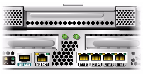
Note - The device naming for the NICs is reported differently by different interfaces and operating systems.
B.2.3 NIC Naming
TABLE B-1 illustrates the default naming used by the various operating systems for the four NICs shown in FIGURE B-1.
TABLE B-1 Sun Netra X4250 NIC Naming
Net 0
Net 1
Net 2
Net3
BIOS
slot 108
slot 108
slot 108
slot 108
Solaris 10
nge0
nge1
e1000g0
e1000g1
Red Hat Linux
eth2
eth3
eth0
eth1
SUSE Linux
eth0
eth1
eth2
eth3
Windows 2003
net
net2
net3
net4
B.2.3.1 Sun Netra X4250 Server NIC Booting Priority
The order in which the BIOS detects the Ethernet ports during bootup, and the corresponding drivers that control those ports are listed below:
1. NET 0 (Intel E1000 G0)
2. NET 1 (Intel E1000 G1)
3. NET 2 (Intel E1000 G2)
4. NET 3 (Intel E1000 G3)
B.3 BIOS Setup Screens
TABLE B-2 contains summary descriptions of the top-level BIOS setup screens.
TABLE B-2 BIOS Setup Screens Summary
Screen
Description
Section
Main
General product information, including BIOS type, processor, memory, and time and date.
BIOS Main Menu Screens
Advanced
Configuration information for the CPU, memory, IDE, Super IO, trusted computing, USB, PCI, MPS, and event log.
BIOS Advanced Menu Screens
Boot
Configure the boot device priority (hard drives and the optical media drive).
BIOS Boot Menu Screens
Server
Server devices can be configured by the BIOS (if applicable).
BIOS Server Menu Screens
Security
Set or change the user and supervisor passwords.
BIOS Security Menu Screens
Exit
Save changes and exit, discard changes and exit, discard changes, or load optimal or fail-safe defaults.
BIOS Exit Menu Screens
FIGURE B-2 summarizes the BIOS menu tree. See BIOS Setup Menu Screens for examples of each of these screens.
FIGURE B-2 BIOS Utility Menu Tree
[ D ]
B.3.1 BIOS Setup Menu Screens
The following figures show sample Sun Netra X4250 server BIOS Setup Utility screens. All settings are set to the optimal default at startup.
Note - The screens shown are examples. The version numbers and the screen items and selections shown are subject to change over the life of the product.
B.3.1.1 BIOS Main Menu Screens
The BIOS Main screens provide general product information, including BIOS type, processor type, memory, and time and date.
The Sun Netra X4250 server from Oracle has the following BIOS Main screens.
FIGURE B-3 BIOS Setup Utility: Main - System Overview
FIGURE B-4 BIOS Setup Utility: Main - Product Information
B.3.1.2 BIOS Advanced Menu Screens
The BIOS Advanced screens provide detailed configuration information for the CPU, memory, IDE, Super IO, trusted computing, USB, PCI, MPS, and other system information.
The Sun Netra X4250 server has the following BIOS Advanced screens:
FIGURE B-5 BIOS Setup Utility: Advanced
FIGURE B-6 BIOS Setup Utility: Advanced - CPU Settings
FIGURE B-7 BIOS Setup Utility: Advanced - System Memory Settings
FIGURE B-8 BIOS Setup Utility: Advanced - IDE Configuration
FIGURE B-9 BIOS Setup Utility: Advanced - Super IO Configuration
FIGURE B-10 BIOS Setup Utility: Advanced - Trusted Computing
FIGURE B-11 Bios Setup Utility: Advanced - USB Configuration
FIGURE B-12 BIOS Setup Utility: Advanced - USB Configuration 2
FIGURE B-13 BIOS Setup Utility: Advanced- PCI Configuration
FIGURE B-14 BIOS Setup Utility: Advanced- MPS Configuration
FIGURE B-15 BIOS Setup Utility: Advanced- Event Log Configuration
B.3.1.3 BIOS Boot Menu Screens
The BIOS Boot screens enable you to configure the boot device priority (hard drives and the optical media drives).
The Sun Netra X4250 server has the following BIOS Boot screens.
FIGURE B-16 BIOS Setup Utility: Boot
FIGURE B-17 BIOS Setup Utility: Boot Settings Configuration
FIGURE B-18 BIOS Setup Utility: Boot Device Priority
FIGURE B-19 BIOS Setup Utility: Boot Hard Drives
FIGURE B-20 BIOS Setup Utility: Boot CD/DVD Drives
B.3.1.4 BIOS Server Menu Screens
The BIOS Server screens enable you to configure Server devices (if applicable).
Note - The term BMC that may be displayed on some screens refers to the SP (service processor).
The Sun Netra X4250 server has the following BIOS Server screens.
FIGURE B-21 BIOS Setup Utility: Server
FIGURE B-22 BIOS Setup Utility: Server - Bottom of Scroll
FIGURE B-23 BIOS Setup Utility: Server - LAN Configuration
FIGURE B-24 BIOS Setup Utility: Server - LAN Configuration - Reset SP (BMC) Password
FIGURE B-25 BIOS Setup Utility: Server - Enable Remote Access
FIGURE B-26 Bios Setup Utility: Server - View SP Event Log
FIGURE B-27 BIOS Setup Utility: Server - Clear SP Event Log
B.3.1.5 BIOS Security Menu Screens
The BIOS Security screens enable you to set or change the user and supervisor passwords.
The Sun Netra X4250 server has the following BIOS Security screens:
FIGURE B-28 BIOS Setup Utility: Security -Menu
B.3.1.6 BIOS Exit Menu Screens
The BIOS Exit screens enable you to save changes and exit, discard changes and exit, discard changes, or load optimal or fail-safe defaults.
The Sun Netra X4250 server has the following BIOS Exit screens:
FIGURE B-29 BIOS Setup Utility: Exit
FIGURE B-30 BIOS Setup Utility: Exit - Save Configuration Changes
FIGURE B-31 BIOS Setup Utility: Exit - Discard Changes
FIGURE B-32 BIOS Setup Utility: Exit - Discard Changes, Do Not Exit
FIGURE B-33 BIOS Setup Utility: Exit - Load Optimal Defaults
FIGURE B-34 BIOS Setup Utility: Exit - Load Fail-Safe Defaults
B.4 Viewing Event Logs
Use this procedure to view the BIOS event log and the SP system event log.
1. To turn on main power mode (all components powered on) if necessary, use a ball point pen or other stylus to press and release the Power button on the server front panel (FIGURE 1-6).
When main power is applied to the full server, the Power OK LED next to the Power button lights and remains lit.
2. Enter the BIOS Setup utility by pressing the F2 key while the system is performing the power-on self-test (POST).
The BIOS Main menu screen is displayed (FIGURE B-4).
3. View the BIOS event log.
a. From the BIOS Main menu screen, select Advanced.
The Advanced Settings screen is displayed (FIGURE B-5).
b. From the Advanced Settings screen, select Event Log Configuration.
The Event Logging Details screen is displayed (FIGURE B-15).
c. From the Event Logging Details screen, select View Event Log.
All unread events are displayed (FIGURE B-35).
4. View the SP system event log.
a. From the BIOS Main menu screen, select Server.
The Server screen is displayed (FIGURE B-21).
b. From the Server screen, select View SP System Event Log.
All events are displayed (FIGURE B-35).
FIGURE B-35 Event Log Screen
B.5 Setting Watchdog Timers
The watchdog timers (WDT) allow the service processor (SP) to reset or power down the system if the BIOS or operating system (OS) crashes or hangs.
Use this procedure to set the either the SP BIOS WatchDog Timer or the SP OS WatchDog Timer.
1. Enter the BIOS Setup utility by pressing the F2 key while the system is performing the power-on self-test (POST).
The BIOS Main menu screen is displayed (FIGURE B-4).
2. From the BIOS Main menu screen, select Server.
3. The Server screen is displayed (FIGURE B-21).
4. From the Server screen, select either SP BIOS WatchDog Timer Action or SP OS WatchDog Timer Action.
5. The Options screen is displayed (FIGURE B-36).
6. From the Options screen, select the desired action.
7. From the Server screen, set either the SP BIOS WatchDog Time Out or SP OS WatchDog Time Out value, if applicable.
8. Save the changes and exit BIOS Utility by pressing F10.
Alternately, you can select the Exit screen, then select Save Changes and Exit.
FIGURE B-36 SP Watch Dog Timer Options Screen
B.6 Power-On Self-Test (POST)
The system BIOS provides a rudimentary power-on self-test. The basic devices required for the server to operate are checked, memory is tested, the disk controller and attached disks are probed and enumerated, and the two Intel dual Gigabit Ethernet controllers are initialized.
The progress of the self-test is indicated by a series of POST codes. These codes are displayed at the bottom right corner of the system’s VGA screen (once the self-test has progressed far enough to initialize the system video). However, the codes are displayed as the self-test runs and scroll off of the screen too quickly to be read. An alternate method of displaying the POST codes is to redirect the output of the console to a serial port (see Redirecting Console Output).
B.6.1 How BIOS POST Memory Testing Works
The BIOS POST memory testing is performed as follows:
1. The first megabyte of DRAM is tested by the BIOS before the BIOS code is shadowed (that is, copied from ROM to DRAM).
2. Once executing out of DRAM, the BIOS performs a simple memory test (a write-read of every location with the pattern 55aa55aa).
Note - Enabling Quick Boot causes the BIOS to skip the memory test. See Changing POST Options for more information.
Note - Because the server can contain up to 64 MByte of memory, the memory test can take several minutes. You can cancel POST testing by pressing any key during POST.
3. The BIOS polls the memory controllers for both correctable and uncorrectable memory errors and logs those errors into the service processor.
B.6.2 Redirecting Console Output
Use the following instructions to access the service processor and redirect the console output so that the BIOS POST codes can be read.
1. Initialize the BIOS Setup utility by pressing the F2 key while the system is performing the power-on self-test (POST).
The BIOS Main menu screen is displayed.
2. Select the Advanced menu tab.
The Advanced Settings screen is displayed.
3. Select IPMI 2.0 Configuration.
The IPMI 2.0 Configuration screen is displayed.
4. Select the LAN Configuration menu item.
The LAN Configuration screen displays the service processor’s IP address.
5. To configure the service processor’s IP address (optional):
a. Select the IP Assignment option that you want to use (DHCP or Static).
If you choose DHCP, the server’s IP address is retrieved from your network’s DHCP server and displayed using the following format:
Current IP address in BMC : xxx.xxx.xxx.xxx
If you choose Static to assign the IP address manually, perform the following steps:
i. Type the IP address in the IP Address field.
You can also enter the subnet mask and default gateway settings in their respective fields.
ii. Select Commit and press Return to commit the changes.
iii. Select Refresh and press Return to see your new settings displayed in the Current IP address in BMC field.
6. Start a web browser and type the service processor’s IP address in the browser’s URL field.
7. When you are prompted for a user name and password, type the following:
User Name: root
Password: password
The Sun Integrated Lights Out Manager main GUI screen is displayed.
8. Click the Remote Control tab.
9. Click the Redirection tab.
10. Set the color depth for the redirection console at either 6 or 8 bits.
Click the Start Redirection button.
11. When you are prompted for a user name and password, type the following:
User Name: root
Password: password
The current POST screen is displayed.
B.6.3 Changing POST Options
These instructions are optional, but you can use them to change the operations that the server performs during POST testing. To change POST options:
1. Initialize the BIOS Setup utility by pressing the F2 key while the system is performing the power-on self-test (POST).
The BIOS Main menu screen is displayed (FIGURE B-3).
2. Select Boot.
The Boot Settings screen is displayed (FIGURE B-16).
3. Select Boot Settings Configuration.
The Boot Settings Configuration screen is displayed (FIGURE B-17).
4. On the Boot Settings Configuration screen, there are several options that you can enable or disable:
Quick Boot - This option is disabled by default. If you enable this option, the BIOS skips certain tests while booting, such as the extensive memory test. This action decreases the time it takes for the system to boot.
Quiet Boot - This option is disabled by default. If you enable this option, the Sun Microsystems logo is displayed instead of POST codes.
Add On ROM Display Mode - This option is set to Force BIOS by default. This option has effect only if you have also enabled the Quiet Boot option, but this option controls whether output from the Option ROM is displayed. The two settings for this option are as follows:
Force BIOS - Remove the Sun logo and display Option ROM output.
Keep Current - Do not remove the Sun logo. The Option ROM output is not displayed.
Boot Num-Lock - This option is on by default (keyboard Num-Lock is turned on during boot). If you set this to off, the keyboard Num-Lock is not turned on during boot.
Wait for F1 if Error - This option is disabled by default. If you enable this option, the system will pause if an error is found during POST and will only resume when you press the F1 key.
Interrupt 19 Capture - This option is reserved for future use. Do not change.
Default Boot Order - The letters in the brackets represent the boot devices. To see the letters defined, position your cursor over the field and read the definition in the right side of the screen.
B.6.4 POST Codes
TABLE B-3 contains descriptions of each of the POST codes, listed in the same order in which they are generated. These POST codes appear as a four-digit string that is a combination of two-digit output from primary I/O port 80 and two-digit output from secondary I/O port 81. In the POST codes listed in TABLE B-3, the first two digits are from port 81 and the last two digits are from port 80.
TABLE B-3 POST Codes
Post Code
Description
00d0
Coming out of POR, PCI configuration space initialization, enabling 8111’s SMBus.
00d1
Keyboard controller BAT, waking up from PM, saving power-on CPUID in scratch CMOS.
00d2
Disabling cache, full memory sizing, and verifying that flat mode is enabled.
00d3
Memory detections and sizing in boot block, cache disabled, I/O APIC enabled.
01d4
Testing base 512KB memory. Adjusting policies and cache first 8MB.
01d5
Boot block code is copied from ROM to lower RAM. BIOS is now executing out of RAM.
01d6
Key sequence and OEM specific method is checked to determine if BIOS recovery is forced. If next code is E0, BIOS recovery is being executed. Main BIOS checksum is tested.
01d7
Restoring CPUID: Moving boot block-runtime interface module to RAM: determining whether to execute serial flash.
01d8
Decompressing runtime module into RAM. Storing CPUID information in memory.
01d9
Copying main BIOS into memory.
01da
Giving control to BIOS POST.
0004
Checking CMOS diagnostic byte to determine if battery power is OK and CMOS checksum is OK. If the CMOS checksum is bad, update CMOS with power-on default values.
00c2
Setting up boot strap processor for POST. This action includes frequency calculation, loading BSP microcode, and applying user requested value for GART Error Reporting setup question.
00c3
Errata workarounds applied to the BSP (No. 78 and No. 110).
00c6
Re-enable cache for boot strap processor, and apply workarounds in the BSP for errata No. 106, No. 107, No. 69, and No. 63 if appropriate.
00c7
HT sets link frequencies and widths to their final values.
000a
Initializing the 8042 compatible keyboard controller.
000c
Detecting the presence of keyboard in KBC port.
000e
Testing and initialization of different input devices. Traps the INT09h vector, so that the POST INT09h handler gets control for IRQ1.
8600
Preparing CPU for booting to OS by copying all of the context of the BSP to all application processors present. Note: APs are left in the CLI HLT state.
de00
Preparing CPU for booting to OS by copying all of the context of the BSP to all application processors present. Note: APs are left in the CLI HLT state.
8613
Initializing PM regs and PM PCI regs at early-POST. Initialize multihost bridge, if system supports it. Setup ECC options before memory clearing. Enable PCI-X clock lines in the 8131.
0024
Decompressing and initializing any platform specific BIOS modules.
862a
BBS ROM initialization.
002a
Generic Device Initialization Manager (DIM) - Disable all devices.
042a
ISA PnP devices - Disable all devices.
052a
PCI devices - Disable all devices.
122a
ISA devices - Static device initialization.
152a
PCI devices - Static device initialization.
252a
PCI devices - Output device initialization.
202c
Initializing different devices. Detecting and initializing the video adapter installed in the system that have optional ROMs.
002e
Initializing all the output devices.
0033
Initializing the silent boot module. Set the window for displaying text information.
0037
Displaying sign-on message, CPU information, setup key message, and any OEM specific information.
4538
PCI devices - IPL device initialization.
5538
PCI devices - General device initialization.
8600
Preparing CPU for booting to OS by copying all of the context of the BSP to all application processors present. Note: APs are left in the CLI HLT state.
B.6.5 POST Code Checkpoints
The POST code checkpoints are the largest set of checkpoints during the BIOS pre-boot process. TABLE B-4 describes the type of checkpoints that might occur during the POST portion of the BIOS. These two-digit checkpoints are the output from primary I/O port 80.
TABLE B-4 POST Code Checkpoints
Post Code
Description
03
Global initialization before the execution of actual BIOS POST. Initialize BIOS Data Area (BDA) variables to their default values. Initialize POST data variables. NMI, parity, video for EGA, and DMA controllers are disabled at this point.
04
Checks CMOS diagnostic byte to verify that battery power and CMOS checksum is OK. Verify CMOS checksum manually by reading storage area. If the CMOS checksum is bad, update CMOS with power-on default values and clear passwords. Initialize status register A. Initializes data variables that are based on CMOS setup questions. Initializes both the 8259 compatible PICs in the system.
05
Initializes the interrupt controlling hardware (generally PIC) and interrupt vector table.
06
Does read-write test to CH-2 count reg. Initialize CH-0 as system timer. Install the POSTINT1Ch handler. Enable IRQ-0 in PIC for system timer interrupt. Traps INT1Ch vector to POSTINT1ChHandlerBlock.
C0
Early CPU Init Start-Disable Cache-Init Local APIC.
C1
Sets up boot strap processor information.
C2
Sets up boot strap processor for POST. This action includes frequency calculation, loading BSP microcode, and applying user requested value for GART Error Reporting setup question.
C3
Errata workarounds applied to the BSP (No. 78 & No. 110).
C5
Enumerates and sets up application processors. This action includes microcode loading, and workarounds for errata (No. 78, No. 110, No. 106, No. 107, No. 69, No. 63).
C6
Re-enable cache for boot strap processor, and apply workarounds in the BSP for errata No. 106, No. 107, No. 69, and No. 63 if appropriate. In case of mixed CPU steppings, errors are sought and logged, and an appropriate frequency for all CPUs is found and applied. Note: APs are left in the CLI HLT state.
C7
The HT sets link frequencies and widths to their final values. This routine gets called after CPU frequency has been calculated to prevent bad programming.
0A
Initializes the 8042 compatible keyboard controller.
0B
Detects the presence of PS/2 mouse.
0C
Detects the presence of keyboard in KBC port.
0E
Testing and initialization of different input Devices. Also, update the kernel variables. Traps the INT09h vector, so that the POST INT09h handler gets control for IRQ1. Decompress all available language, BIOS logo, and silent logo modules.
13
Initializes PM regs and PM PCI regs at Early-POST. Initialize multihost bridge, if system supports it. Set up ECC options before memory clearing. REDIRECTION causes corrected data to written to RAM immediately. CHIPKILL provides 4 bit error det/corr of x4 type memory. Enable PCI-X clock lines in the 8131.
20
Relocates all the CPUs to a unique SMBASE address. The BSP will be set to have its entry point at A000:0. If fewer than 5 CPU sockets are present on a board, subsequent CPUs entry points will be separated by 8000h bytes. If more than 4 CPU sockets are present, entry points are separated by 200h bytes. CPU module will be responsible for the relocation of the CPU to correct address. Note: APs are left in the INIT state.
24
Decompresses and initializes any platform specific BIOS modules.
30
Initializes System Management Interrupt.
2A
Initializes different devices through DIM.
2C
Initializes different devices. Detects and initializes the video adapter installed in the system that have optional ROMs.
2E
Initializes all the output devices.
31
Allocates memory for ADM module and decompress it. Gives control to ADM module for initialization. Initializes language and font modules for ADM. Activate ADM module.
33
Initializes the silent boot module. Set the window for displaying text information.
37
Displaying sign-on message, CPU information, setup key message, and any OEM specific information.
38
Initializes different devices through DIM.
39
Initializes DMAC-1 and DMAC-2.
3A
Initializes RTC date and time.
3B
Tests for total memory installed in the system. Also, Check for DEL or ESC keys to limit memory test. Displays total memory in the system.
3C
By this point, RAM read-write test is completed, program memory holes or handle any adjustments needed in RAM size with respect to NB. Tests if HT module found an error in boot block and CPU compatibility for MP environment.
40
Detects different devices (Parallel ports, serial ports, and coprocessor in CPU, etc.) successfully installed in the system and update the BDA, EBDA, etc.
50
Programming the memory hole or any kind of implementation that needs an adjustment in system RAM size if needed.
52
Updates CMOS memory size from memory found in memory test. Allocates memory for Extended BIOS Data Area from base memory.
60
Initializes NUM-LOCK status and programs the KBD typematic rate.
75
Initializes Int-13 and prepares for IPL detection.
78
Initializes IPL devices controlled by BIOS and option ROMs.
7A
Initializes remaining option ROMs.
7C
Generates and writes contents of ESCD in NVRAM.
84
Logs errors encountered during POST.
85
Displays errors to the user and gets the user response for error.
87
Executes BIOS setup if needed or requested.
8C
After all device initialization is done, programmed any user selectable parameters relating to NB/SB, such as timing parameters, noncacheable regions, and the shadow RAM cacheability, and do any other NB/SB/PCIX/OEM specific programming needed during Late-POST. Background scrubbing for DRAM, and L1 and L2 caches are set up based on setup questions. Get the DRAM scrub limits from each node. Workaround for erratum No. 101 applied here.
8D
Builds ACPI tables (if ACPI is supported).
8E
Programs the peripheral parameters. Enable/Disable NMI as selected.
90
Late POST initialization of system management interrupt.
A0
Checks boot password if installed.
A1
Clean-up work needed before booting to OS.
A2
Takes care of runtime image preparation for different BIOS modules. Fills the free area in F000h segment with 0FFh. Initializes the Microsoft IRQ routing table. Prepares the runtime language module. Disables the system configuration display if needed.
A4
Initializes runtime language module.
A7
Displays the system configuration screen if enabled. Initializes the CPUs before boot, which includes the programming of the MTRRs.
A8
Prepares CPU for OS boot including final MTRR values.
A9
Waits for user input at config display if needed.
AA
Uninstalls POST INT1Ch vector and INT09h vector. Deinitializes the ADM module.
AB
Prepares BBS for Int 19 boot.
AC
Any kind of chipsets (NB/SB) specific programming needed during End- POST, just before giving control to runtime code booting to OS. Programmed the system BIOS (0F0000h shadow RAM) cacheability. Ported to handle any OEM specific programming needed during End-POST. Copies OEM specific data from POST_DSEG to RUN_CSEG.
B1
Saves system context for ACPI.
00
Prepares CPU for booting to OS by copying all of the context of the BSP to all application processors present. Note: APs are left in the CLIHLT state.
61-70
OEM POST error. This range is reserved for chipset vendors and system manufacturers. The error associated with this value might be different from one platform to the next.
Copyright © 2012, PERALTA COMPUTERS. All rights reserved.
The Basic Input/Output System (BIOS) has a Setup utility stored in the BIOS flash memory. The configured data is provided with context-sensitive help and is stored in the system's battery-backed CMOS RAM. If the configuration stored in the CMOS RAM is invalid, the BIOS settings default to the original state specified at the factory.
Using BIOS Menu Items
BIOS Considerations
BIOS Setup Screens
Viewing Event Logs
Graphic showing the Event Logging screen.
Power-On Self-Test (POST)
B.1 Using BIOS Menu Items
You can access BIOS configuration screens from the following interfaces:
Use a USB keyboard, mouse, and VGA monitor connected directly to the server.
Use a terminal (or terminal emulator connected to a computer) through the serial port on the back panel of the server.
To access BIOS configuration screens and change the system’s parameters, do the following steps:
1. Enter the BIOS Setup utility by pressing the F2 key while the system is performing the power-on self-test (POST).
When BIOS is started, the main BIOS Setup menu screen is displayed.
2. Highlight the field to be modified using the arrow and Tab keys.
Use the left and right arrow keys to move sequentially back and forth through the menu screens. Fields that can be reconfigured are displayed in color. All other fields are nonconfigurable.
Use the Up and Down keys on the keyboard, to scroll through a menu.
Use the Tab key to move back and forth across columns.
3. Press Enter to select the field.
A dialog box shows the available options.
4. Modify the Setup field and close the screen.
5. If you need to modify other setup parameters, use the arrow and Tab keys to navigate to the desired screen and menu item, and then repeat Step 1 through Step 4.
Otherwise, go to Step 6.
6. Press and release the right arrow key until the Exit menu screen appears.
7. Follow the instructions on the Exit menu screen to save your changes and exit the Setup utility.
B.2 BIOS Considerations
This section contains information and considerations regarding the system BIOS.
B.2.1 Peripheral Component Interconnect (PCI) Card Slot Booting Priority
For the locations of the Sun Netra X4250 server PCI slots, see Replacing PCI-X and PCIe Cards.
The slots for the PCI cards are detected by the BIOS during startup in the following order:
1. PCIe Slot 1
2. PCIe Slot 2
3. PCI-X Slot 3
4. PCI-X Slot 4
5. PCIe Slot 5
B.2.2 Ethernet Port (NIC) Device and Driver Naming
These servers each have four 10/100/1000BASE-T Gigabit Ethernet ports (NICs). The chassis labeling of the physical ports is shown in FIGURE B-1.
FIGURE B-1 Ethernet Ports
Note - The device naming for the NICs is reported differently by different interfaces and operating systems.
B.2.3 NIC Naming
TABLE B-1 illustrates the default naming used by the various operating systems for the four NICs shown in FIGURE B-1.
TABLE B-1 Sun Netra X4250 NIC Naming
Net 0
Net 1
Net 2
Net3
BIOS
slot 108
slot 108
slot 108
slot 108
Solaris 10
nge0
nge1
e1000g0
e1000g1
Red Hat Linux
eth2
eth3
eth0
eth1
SUSE Linux
eth0
eth1
eth2
eth3
Windows 2003
net
net2
net3
net4
B.2.3.1 Sun Netra X4250 Server NIC Booting Priority
The order in which the BIOS detects the Ethernet ports during bootup, and the corresponding drivers that control those ports are listed below:
1. NET 0 (Intel E1000 G0)
2. NET 1 (Intel E1000 G1)
3. NET 2 (Intel E1000 G2)
4. NET 3 (Intel E1000 G3)
B.3 BIOS Setup Screens
TABLE B-2 contains summary descriptions of the top-level BIOS setup screens.
TABLE B-2 BIOS Setup Screens Summary
Screen
Description
Section
Main
General product information, including BIOS type, processor, memory, and time and date.
BIOS Main Menu Screens
Advanced
Configuration information for the CPU, memory, IDE, Super IO, trusted computing, USB, PCI, MPS, and event log.
BIOS Advanced Menu Screens
Boot
Configure the boot device priority (hard drives and the optical media drive).
BIOS Boot Menu Screens
Server
Server devices can be configured by the BIOS (if applicable).
BIOS Server Menu Screens
Security
Set or change the user and supervisor passwords.
BIOS Security Menu Screens
Exit
Save changes and exit, discard changes and exit, discard changes, or load optimal or fail-safe defaults.
BIOS Exit Menu Screens
FIGURE B-2 summarizes the BIOS menu tree. See BIOS Setup Menu Screens for examples of each of these screens.
FIGURE B-2 BIOS Utility Menu Tree
[ D ]
B.3.1 BIOS Setup Menu Screens
The following figures show sample Sun Netra X4250 server BIOS Setup Utility screens. All settings are set to the optimal default at startup.
Note - The screens shown are examples. The version numbers and the screen items and selections shown are subject to change over the life of the product.
B.3.1.1 BIOS Main Menu Screens
The BIOS Main screens provide general product information, including BIOS type, processor type, memory, and time and date.
The Sun Netra X4250 server from Oracle has the following BIOS Main screens.
FIGURE B-3 BIOS Setup Utility: Main - System Overview
FIGURE B-4 BIOS Setup Utility: Main - Product Information
B.3.1.2 BIOS Advanced Menu Screens
The BIOS Advanced screens provide detailed configuration information for the CPU, memory, IDE, Super IO, trusted computing, USB, PCI, MPS, and other system information.
The Sun Netra X4250 server has the following BIOS Advanced screens:
FIGURE B-5 BIOS Setup Utility: Advanced
FIGURE B-6 BIOS Setup Utility: Advanced - CPU Settings
FIGURE B-7 BIOS Setup Utility: Advanced - System Memory Settings
FIGURE B-8 BIOS Setup Utility: Advanced - IDE Configuration
FIGURE B-9 BIOS Setup Utility: Advanced - Super IO Configuration
FIGURE B-10 BIOS Setup Utility: Advanced - Trusted Computing
FIGURE B-11 Bios Setup Utility: Advanced - USB Configuration
FIGURE B-12 BIOS Setup Utility: Advanced - USB Configuration 2
FIGURE B-13 BIOS Setup Utility: Advanced- PCI Configuration
FIGURE B-14 BIOS Setup Utility: Advanced- MPS Configuration
FIGURE B-15 BIOS Setup Utility: Advanced- Event Log Configuration
B.3.1.3 BIOS Boot Menu Screens
The BIOS Boot screens enable you to configure the boot device priority (hard drives and the optical media drives).
The Sun Netra X4250 server has the following BIOS Boot screens.
FIGURE B-16 BIOS Setup Utility: Boot
FIGURE B-17 BIOS Setup Utility: Boot Settings Configuration
FIGURE B-18 BIOS Setup Utility: Boot Device Priority
FIGURE B-19 BIOS Setup Utility: Boot Hard Drives
FIGURE B-20 BIOS Setup Utility: Boot CD/DVD Drives
B.3.1.4 BIOS Server Menu Screens
The BIOS Server screens enable you to configure Server devices (if applicable).
Note - The term BMC that may be displayed on some screens refers to the SP (service processor).
The Sun Netra X4250 server has the following BIOS Server screens.
FIGURE B-21 BIOS Setup Utility: Server
FIGURE B-22 BIOS Setup Utility: Server - Bottom of Scroll
FIGURE B-23 BIOS Setup Utility: Server - LAN Configuration
FIGURE B-24 BIOS Setup Utility: Server - LAN Configuration - Reset SP (BMC) Password
FIGURE B-25 BIOS Setup Utility: Server - Enable Remote Access
FIGURE B-26 Bios Setup Utility: Server - View SP Event Log
FIGURE B-27 BIOS Setup Utility: Server - Clear SP Event Log
B.3.1.5 BIOS Security Menu Screens
The BIOS Security screens enable you to set or change the user and supervisor passwords.
The Sun Netra X4250 server has the following BIOS Security screens:
FIGURE B-28 BIOS Setup Utility: Security -Menu
B.3.1.6 BIOS Exit Menu Screens
The BIOS Exit screens enable you to save changes and exit, discard changes and exit, discard changes, or load optimal or fail-safe defaults.
The Sun Netra X4250 server has the following BIOS Exit screens:
FIGURE B-29 BIOS Setup Utility: Exit
FIGURE B-30 BIOS Setup Utility: Exit - Save Configuration Changes
FIGURE B-31 BIOS Setup Utility: Exit - Discard Changes
FIGURE B-32 BIOS Setup Utility: Exit - Discard Changes, Do Not Exit
FIGURE B-33 BIOS Setup Utility: Exit - Load Optimal Defaults
FIGURE B-34 BIOS Setup Utility: Exit - Load Fail-Safe Defaults
B.4 Viewing Event Logs
Use this procedure to view the BIOS event log and the SP system event log.
1. To turn on main power mode (all components powered on) if necessary, use a ball point pen or other stylus to press and release the Power button on the server front panel (FIGURE 1-6).
When main power is applied to the full server, the Power OK LED next to the Power button lights and remains lit.
2. Enter the BIOS Setup utility by pressing the F2 key while the system is performing the power-on self-test (POST).
The BIOS Main menu screen is displayed (FIGURE B-4).
3. View the BIOS event log.
a. From the BIOS Main menu screen, select Advanced.
The Advanced Settings screen is displayed (FIGURE B-5).
b. From the Advanced Settings screen, select Event Log Configuration.
The Event Logging Details screen is displayed (FIGURE B-15).
c. From the Event Logging Details screen, select View Event Log.
All unread events are displayed (FIGURE B-35).
4. View the SP system event log.
a. From the BIOS Main menu screen, select Server.
The Server screen is displayed (FIGURE B-21).
b. From the Server screen, select View SP System Event Log.
All events are displayed (FIGURE B-35).
FIGURE B-35 Event Log Screen
B.5 Setting Watchdog Timers
The watchdog timers (WDT) allow the service processor (SP) to reset or power down the system if the BIOS or operating system (OS) crashes or hangs.
Use this procedure to set the either the SP BIOS WatchDog Timer or the SP OS WatchDog Timer.
1. Enter the BIOS Setup utility by pressing the F2 key while the system is performing the power-on self-test (POST).
The BIOS Main menu screen is displayed (FIGURE B-4).
2. From the BIOS Main menu screen, select Server.
3. The Server screen is displayed (FIGURE B-21).
4. From the Server screen, select either SP BIOS WatchDog Timer Action or SP OS WatchDog Timer Action.
5. The Options screen is displayed (FIGURE B-36).
6. From the Options screen, select the desired action.
7. From the Server screen, set either the SP BIOS WatchDog Time Out or SP OS WatchDog Time Out value, if applicable.
8. Save the changes and exit BIOS Utility by pressing F10.
Alternately, you can select the Exit screen, then select Save Changes and Exit.
FIGURE B-36 SP Watch Dog Timer Options Screen
B.6 Power-On Self-Test (POST)
The system BIOS provides a rudimentary power-on self-test. The basic devices required for the server to operate are checked, memory is tested, the disk controller and attached disks are probed and enumerated, and the two Intel dual Gigabit Ethernet controllers are initialized.
The progress of the self-test is indicated by a series of POST codes. These codes are displayed at the bottom right corner of the system’s VGA screen (once the self-test has progressed far enough to initialize the system video). However, the codes are displayed as the self-test runs and scroll off of the screen too quickly to be read. An alternate method of displaying the POST codes is to redirect the output of the console to a serial port (see Redirecting Console Output).
B.6.1 How BIOS POST Memory Testing Works
The BIOS POST memory testing is performed as follows:
1. The first megabyte of DRAM is tested by the BIOS before the BIOS code is shadowed (that is, copied from ROM to DRAM).
2. Once executing out of DRAM, the BIOS performs a simple memory test (a write-read of every location with the pattern 55aa55aa).
Note - Enabling Quick Boot causes the BIOS to skip the memory test. See Changing POST Options for more information.
Note - Because the server can contain up to 64 MByte of memory, the memory test can take several minutes. You can cancel POST testing by pressing any key during POST.
3. The BIOS polls the memory controllers for both correctable and uncorrectable memory errors and logs those errors into the service processor.
B.6.2 Redirecting Console Output
Use the following instructions to access the service processor and redirect the console output so that the BIOS POST codes can be read.
1. Initialize the BIOS Setup utility by pressing the F2 key while the system is performing the power-on self-test (POST).
The BIOS Main menu screen is displayed.
2. Select the Advanced menu tab.
The Advanced Settings screen is displayed.
3. Select IPMI 2.0 Configuration.
The IPMI 2.0 Configuration screen is displayed.
4. Select the LAN Configuration menu item.
The LAN Configuration screen displays the service processor’s IP address.
5. To configure the service processor’s IP address (optional):
a. Select the IP Assignment option that you want to use (DHCP or Static).
If you choose DHCP, the server’s IP address is retrieved from your network’s DHCP server and displayed using the following format:
Current IP address in BMC : xxx.xxx.xxx.xxx
If you choose Static to assign the IP address manually, perform the following steps:
i. Type the IP address in the IP Address field.
You can also enter the subnet mask and default gateway settings in their respective fields.
ii. Select Commit and press Return to commit the changes.
iii. Select Refresh and press Return to see your new settings displayed in the Current IP address in BMC field.
6. Start a web browser and type the service processor’s IP address in the browser’s URL field.
7. When you are prompted for a user name and password, type the following:
User Name: root
Password: password
The Sun Integrated Lights Out Manager main GUI screen is displayed.
8. Click the Remote Control tab.
9. Click the Redirection tab.
10. Set the color depth for the redirection console at either 6 or 8 bits.
Click the Start Redirection button.
11. When you are prompted for a user name and password, type the following:
User Name: root
Password: password
The current POST screen is displayed.
B.6.3 Changing POST Options
These instructions are optional, but you can use them to change the operations that the server performs during POST testing. To change POST options:
1. Initialize the BIOS Setup utility by pressing the F2 key while the system is performing the power-on self-test (POST).
The BIOS Main menu screen is displayed (FIGURE B-3).
2. Select Boot.
The Boot Settings screen is displayed (FIGURE B-16).
3. Select Boot Settings Configuration.
The Boot Settings Configuration screen is displayed (FIGURE B-17).
4. On the Boot Settings Configuration screen, there are several options that you can enable or disable:
Quick Boot - This option is disabled by default. If you enable this option, the BIOS skips certain tests while booting, such as the extensive memory test. This action decreases the time it takes for the system to boot.
Quiet Boot - This option is disabled by default. If you enable this option, the Sun Microsystems logo is displayed instead of POST codes.
Add On ROM Display Mode - This option is set to Force BIOS by default. This option has effect only if you have also enabled the Quiet Boot option, but this option controls whether output from the Option ROM is displayed. The two settings for this option are as follows:
Force BIOS - Remove the Sun logo and display Option ROM output.
Keep Current - Do not remove the Sun logo. The Option ROM output is not displayed.
Boot Num-Lock - This option is on by default (keyboard Num-Lock is turned on during boot). If you set this to off, the keyboard Num-Lock is not turned on during boot.
Wait for F1 if Error - This option is disabled by default. If you enable this option, the system will pause if an error is found during POST and will only resume when you press the F1 key.
Interrupt 19 Capture - This option is reserved for future use. Do not change.
Default Boot Order - The letters in the brackets represent the boot devices. To see the letters defined, position your cursor over the field and read the definition in the right side of the screen.
B.6.4 POST Codes
TABLE B-3 contains descriptions of each of the POST codes, listed in the same order in which they are generated. These POST codes appear as a four-digit string that is a combination of two-digit output from primary I/O port 80 and two-digit output from secondary I/O port 81. In the POST codes listed in TABLE B-3, the first two digits are from port 81 and the last two digits are from port 80.
TABLE B-3 POST Codes
Post Code
Description
00d0
Coming out of POR, PCI configuration space initialization, enabling 8111’s SMBus.
00d1
Keyboard controller BAT, waking up from PM, saving power-on CPUID in scratch CMOS.
00d2
Disabling cache, full memory sizing, and verifying that flat mode is enabled.
00d3
Memory detections and sizing in boot block, cache disabled, I/O APIC enabled.
01d4
Testing base 512KB memory. Adjusting policies and cache first 8MB.
01d5
Boot block code is copied from ROM to lower RAM. BIOS is now executing out of RAM.
01d6
Key sequence and OEM specific method is checked to determine if BIOS recovery is forced. If next code is E0, BIOS recovery is being executed. Main BIOS checksum is tested.
01d7
Restoring CPUID: Moving boot block-runtime interface module to RAM: determining whether to execute serial flash.
01d8
Decompressing runtime module into RAM. Storing CPUID information in memory.
01d9
Copying main BIOS into memory.
01da
Giving control to BIOS POST.
0004
Checking CMOS diagnostic byte to determine if battery power is OK and CMOS checksum is OK. If the CMOS checksum is bad, update CMOS with power-on default values.
00c2
Setting up boot strap processor for POST. This action includes frequency calculation, loading BSP microcode, and applying user requested value for GART Error Reporting setup question.
00c3
Errata workarounds applied to the BSP (No. 78 and No. 110).
00c6
Re-enable cache for boot strap processor, and apply workarounds in the BSP for errata No. 106, No. 107, No. 69, and No. 63 if appropriate.
00c7
HT sets link frequencies and widths to their final values.
000a
Initializing the 8042 compatible keyboard controller.
000c
Detecting the presence of keyboard in KBC port.
000e
Testing and initialization of different input devices. Traps the INT09h vector, so that the POST INT09h handler gets control for IRQ1.
8600
Preparing CPU for booting to OS by copying all of the context of the BSP to all application processors present. Note: APs are left in the CLI HLT state.
de00
Preparing CPU for booting to OS by copying all of the context of the BSP to all application processors present. Note: APs are left in the CLI HLT state.
8613
Initializing PM regs and PM PCI regs at early-POST. Initialize multihost bridge, if system supports it. Setup ECC options before memory clearing. Enable PCI-X clock lines in the 8131.
0024
Decompressing and initializing any platform specific BIOS modules.
862a
BBS ROM initialization.
002a
Generic Device Initialization Manager (DIM) - Disable all devices.
042a
ISA PnP devices - Disable all devices.
052a
PCI devices - Disable all devices.
122a
ISA devices - Static device initialization.
152a
PCI devices - Static device initialization.
252a
PCI devices - Output device initialization.
202c
Initializing different devices. Detecting and initializing the video adapter installed in the system that have optional ROMs.
002e
Initializing all the output devices.
0033
Initializing the silent boot module. Set the window for displaying text information.
0037
Displaying sign-on message, CPU information, setup key message, and any OEM specific information.
4538
PCI devices - IPL device initialization.
5538
PCI devices - General device initialization.
8600
Preparing CPU for booting to OS by copying all of the context of the BSP to all application processors present. Note: APs are left in the CLI HLT state.
B.6.5 POST Code Checkpoints
The POST code checkpoints are the largest set of checkpoints during the BIOS pre-boot process. TABLE B-4 describes the type of checkpoints that might occur during the POST portion of the BIOS. These two-digit checkpoints are the output from primary I/O port 80.
TABLE B-4 POST Code Checkpoints
Post Code
Description
03
Global initialization before the execution of actual BIOS POST. Initialize BIOS Data Area (BDA) variables to their default values. Initialize POST data variables. NMI, parity, video for EGA, and DMA controllers are disabled at this point.
04
Checks CMOS diagnostic byte to verify that battery power and CMOS checksum is OK. Verify CMOS checksum manually by reading storage area. If the CMOS checksum is bad, update CMOS with power-on default values and clear passwords. Initialize status register A. Initializes data variables that are based on CMOS setup questions. Initializes both the 8259 compatible PICs in the system.
05
Initializes the interrupt controlling hardware (generally PIC) and interrupt vector table.
06
Does read-write test to CH-2 count reg. Initialize CH-0 as system timer. Install the POSTINT1Ch handler. Enable IRQ-0 in PIC for system timer interrupt. Traps INT1Ch vector to POSTINT1ChHandlerBlock.
C0
Early CPU Init Start-Disable Cache-Init Local APIC.
C1
Sets up boot strap processor information.
C2
Sets up boot strap processor for POST. This action includes frequency calculation, loading BSP microcode, and applying user requested value for GART Error Reporting setup question.
C3
Errata workarounds applied to the BSP (No. 78 & No. 110).
C5
Enumerates and sets up application processors. This action includes microcode loading, and workarounds for errata (No. 78, No. 110, No. 106, No. 107, No. 69, No. 63).
C6
Re-enable cache for boot strap processor, and apply workarounds in the BSP for errata No. 106, No. 107, No. 69, and No. 63 if appropriate. In case of mixed CPU steppings, errors are sought and logged, and an appropriate frequency for all CPUs is found and applied. Note: APs are left in the CLI HLT state.
C7
The HT sets link frequencies and widths to their final values. This routine gets called after CPU frequency has been calculated to prevent bad programming.
0A
Initializes the 8042 compatible keyboard controller.
0B
Detects the presence of PS/2 mouse.
0C
Detects the presence of keyboard in KBC port.
0E
Testing and initialization of different input Devices. Also, update the kernel variables. Traps the INT09h vector, so that the POST INT09h handler gets control for IRQ1. Decompress all available language, BIOS logo, and silent logo modules.
13
Initializes PM regs and PM PCI regs at Early-POST. Initialize multihost bridge, if system supports it. Set up ECC options before memory clearing. REDIRECTION causes corrected data to written to RAM immediately. CHIPKILL provides 4 bit error det/corr of x4 type memory. Enable PCI-X clock lines in the 8131.
20
Relocates all the CPUs to a unique SMBASE address. The BSP will be set to have its entry point at A000:0. If fewer than 5 CPU sockets are present on a board, subsequent CPUs entry points will be separated by 8000h bytes. If more than 4 CPU sockets are present, entry points are separated by 200h bytes. CPU module will be responsible for the relocation of the CPU to correct address. Note: APs are left in the INIT state.
24
Decompresses and initializes any platform specific BIOS modules.
30
Initializes System Management Interrupt.
2A
Initializes different devices through DIM.
2C
Initializes different devices. Detects and initializes the video adapter installed in the system that have optional ROMs.
2E
Initializes all the output devices.
31
Allocates memory for ADM module and decompress it. Gives control to ADM module for initialization. Initializes language and font modules for ADM. Activate ADM module.
33
Initializes the silent boot module. Set the window for displaying text information.
37
Displaying sign-on message, CPU information, setup key message, and any OEM specific information.
38
Initializes different devices through DIM.
39
Initializes DMAC-1 and DMAC-2.
3A
Initializes RTC date and time.
3B
Tests for total memory installed in the system. Also, Check for DEL or ESC keys to limit memory test. Displays total memory in the system.
3C
By this point, RAM read-write test is completed, program memory holes or handle any adjustments needed in RAM size with respect to NB. Tests if HT module found an error in boot block and CPU compatibility for MP environment.
40
Detects different devices (Parallel ports, serial ports, and coprocessor in CPU, etc.) successfully installed in the system and update the BDA, EBDA, etc.
50
Programming the memory hole or any kind of implementation that needs an adjustment in system RAM size if needed.
52
Updates CMOS memory size from memory found in memory test. Allocates memory for Extended BIOS Data Area from base memory.
60
Initializes NUM-LOCK status and programs the KBD typematic rate.
75
Initializes Int-13 and prepares for IPL detection.
78
Initializes IPL devices controlled by BIOS and option ROMs.
7A
Initializes remaining option ROMs.
7C
Generates and writes contents of ESCD in NVRAM.
84
Logs errors encountered during POST.
85
Displays errors to the user and gets the user response for error.
87
Executes BIOS setup if needed or requested.
8C
After all device initialization is done, programmed any user selectable parameters relating to NB/SB, such as timing parameters, noncacheable regions, and the shadow RAM cacheability, and do any other NB/SB/PCIX/OEM specific programming needed during Late-POST. Background scrubbing for DRAM, and L1 and L2 caches are set up based on setup questions. Get the DRAM scrub limits from each node. Workaround for erratum No. 101 applied here.
8D
Builds ACPI tables (if ACPI is supported).
8E
Programs the peripheral parameters. Enable/Disable NMI as selected.
90
Late POST initialization of system management interrupt.
A0
Checks boot password if installed.
A1
Clean-up work needed before booting to OS.
A2
Takes care of runtime image preparation for different BIOS modules. Fills the free area in F000h segment with 0FFh. Initializes the Microsoft IRQ routing table. Prepares the runtime language module. Disables the system configuration display if needed.
A4
Initializes runtime language module.
A7
Displays the system configuration screen if enabled. Initializes the CPUs before boot, which includes the programming of the MTRRs.
A8
Prepares CPU for OS boot including final MTRR values.
A9
Waits for user input at config display if needed.
AA
Uninstalls POST INT1Ch vector and INT09h vector. Deinitializes the ADM module.
AB
Prepares BBS for Int 19 boot.
AC
Any kind of chipsets (NB/SB) specific programming needed during End- POST, just before giving control to runtime code booting to OS. Programmed the system BIOS (0F0000h shadow RAM) cacheability. Ported to handle any OEM specific programming needed during End-POST. Copies OEM specific data from POST_DSEG to RUN_CSEG.
B1
Saves system context for ACPI.
00
Prepares CPU for booting to OS by copying all of the context of the BSP to all application processors present. Note: APs are left in the CLIHLT state.
61-70
OEM POST error. This range is reserved for chipset vendors and system manufacturers. The error associated with this value might be different from one platform to the next.
Copyright © 2012, PERALTA COMPUTERS. All rights reserved.
Ethernet Cable - Color Coding Diagram
The information listed here is to assist Network Administrators in the color coding of Ethernet cables. Please be aware that modifying Ethernet cables improperly may cause loss of network connectivity. Use this information at your own risk, and insure all connectors and cables are modified in accordance with standards. The Internet Centre and its affiliates cannot be held liable for the use of this information in whole or in part.
T-568A Straight-Through Ethernet Cable

The TIA/EIA 568-A standard which was ratified in 1995, was replaced by the TIA/EIA 568-B standard in 2002 and has been updated since. Both standards define the T-568A and T-568B pin-outs for using Unshielded Twisted Pair cable and RJ-45 connectors for Ethernet connectivity. The standards and pin-out specification appear to be related and interchangeable, but are not the same and should not be used interchangeably.
T-568B Straight-Through Ethernet Cable

Both the T-568A and the T-568B standard Straight-Through cables are used most often as patch cords for your Ethernet connections. If you require a cable to connect two Ethernet devices directly together without a hub or when you connect two hubs together, you will need to use a Crossover cable instead.
RJ-45 Crossover Ethernet Cable

A good way of remembering how to wire a Crossover Ethernet cable is to wire one end using the T-568A standard and the other end using the T-568B standard. Another way of remembering the color coding is to simply switch the Green set of wires in place with the Orange set of wires. Specifically, switch the solid Green (G) with the solid Orange, and switch the green/white with the orange/white.
Ethernet Cable Instructions:
1. Pull the cable off the reel to the desired length and cut. If you are pulling cables through holes, its easier to attach the RJ-45 plugs after the cable is pulled. The total length of wire segments between a PC and a hub or between two PC's cannot exceed 100 Meters (328 feet) for 100BASE-TX and 300 Meters for 10BASE-T.
2. Start on one end and strip the cable jacket off (about 1") using a stripper or a knife. Be extra careful not to nick the wires, otherwise you will need to start over.
3. Spread, untwist the pairs, and arrange the wires in the order of the desired cable end. Flatten the end between your thumb and forefinger. Trim the ends of the wires so they are even with one another, leaving only 1/2" in wire length. If it is longer than 1/2" it will be out-of-spec and susceptible to crosstalk. Flatten and insure there are no spaces between wires.
4. Hold the RJ-45 plug with the clip facing down or away from you. Push the wires firmly into the plug. Inspect each wire is flat even at the front of the plug. Check the order of the wires. Double check again. Check that the jacket is fitted right against the stop of the plug. Carefully hold the wire and firmly crimp the RJ-45 with the crimper.
5. Check the color orientation, check that the crimped connection is not about to come apart, and check to see if the wires are flat against the front of the plug. If even one of these are incorrect, you will have to start over. Test the Ethernet cable.
Ethernet Cable Tips:
• A straight-thru cable has identical ends.
• A crossover cable has different ends.
• A straight-thru is used as a patch cord in Ethernet connections.
• A crossover is used to connect two Ethernet devices without a hub or for connecting two hubs.
• A crossover has one end with the Orange set of wires switched with the Green set.
• Odd numbered pins are always striped, even numbered pins are always solid colored.
• Looking at the RJ-45 with the clip facing away from you, Brown is always on the right, and pin 1 is on the left.
• No more than 1/2" of the Ethernet cable should be untwisted otherwise it will be susceptible to crosstalk.
• Do not deform, do not bend, do not stretch, do not staple, do not run parallel with power cables, and do not run Ethernet cables near noise inducing components.
Basic Theory:

By looking at a T-568A UTP Ethernet straight-thru cable and an Ethernet crossover cable with a T-568B end, we see that the TX (transmitter) pins are connected to the corresponding RX (receiver) pins, plus to plus and minus to minus. You can also see that both the blue and brown wire pairs on pins 4, 5, 7, and 8 are not used in either standard. What you may not realize is that, these same pins 4, 5, 7, and 8 are not used or required in 100BASE-TX as well. So why bother using these wires, well for one thing its simply easier to make a connection with all the wires grouped together. Otherwise you'll be spending time trying to fit those tiny little wires into each of the corresponding holes in the RJ-45 connector.
T-568A Straight-Through Ethernet Cable
The TIA/EIA 568-A standard which was ratified in 1995, was replaced by the TIA/EIA 568-B standard in 2002 and has been updated since. Both standards define the T-568A and T-568B pin-outs for using Unshielded Twisted Pair cable and RJ-45 connectors for Ethernet connectivity. The standards and pin-out specification appear to be related and interchangeable, but are not the same and should not be used interchangeably.
T-568B Straight-Through Ethernet Cable
Both the T-568A and the T-568B standard Straight-Through cables are used most often as patch cords for your Ethernet connections. If you require a cable to connect two Ethernet devices directly together without a hub or when you connect two hubs together, you will need to use a Crossover cable instead.
RJ-45 Crossover Ethernet Cable
A good way of remembering how to wire a Crossover Ethernet cable is to wire one end using the T-568A standard and the other end using the T-568B standard. Another way of remembering the color coding is to simply switch the Green set of wires in place with the Orange set of wires. Specifically, switch the solid Green (G) with the solid Orange, and switch the green/white with the orange/white.
Ethernet Cable Instructions:
1. Pull the cable off the reel to the desired length and cut. If you are pulling cables through holes, its easier to attach the RJ-45 plugs after the cable is pulled. The total length of wire segments between a PC and a hub or between two PC's cannot exceed 100 Meters (328 feet) for 100BASE-TX and 300 Meters for 10BASE-T.
2. Start on one end and strip the cable jacket off (about 1") using a stripper or a knife. Be extra careful not to nick the wires, otherwise you will need to start over.
3. Spread, untwist the pairs, and arrange the wires in the order of the desired cable end. Flatten the end between your thumb and forefinger. Trim the ends of the wires so they are even with one another, leaving only 1/2" in wire length. If it is longer than 1/2" it will be out-of-spec and susceptible to crosstalk. Flatten and insure there are no spaces between wires.
4. Hold the RJ-45 plug with the clip facing down or away from you. Push the wires firmly into the plug. Inspect each wire is flat even at the front of the plug. Check the order of the wires. Double check again. Check that the jacket is fitted right against the stop of the plug. Carefully hold the wire and firmly crimp the RJ-45 with the crimper.
5. Check the color orientation, check that the crimped connection is not about to come apart, and check to see if the wires are flat against the front of the plug. If even one of these are incorrect, you will have to start over. Test the Ethernet cable.
Ethernet Cable Tips:
• A straight-thru cable has identical ends.
• A crossover cable has different ends.
• A straight-thru is used as a patch cord in Ethernet connections.
• A crossover is used to connect two Ethernet devices without a hub or for connecting two hubs.
• A crossover has one end with the Orange set of wires switched with the Green set.
• Odd numbered pins are always striped, even numbered pins are always solid colored.
• Looking at the RJ-45 with the clip facing away from you, Brown is always on the right, and pin 1 is on the left.
• No more than 1/2" of the Ethernet cable should be untwisted otherwise it will be susceptible to crosstalk.
• Do not deform, do not bend, do not stretch, do not staple, do not run parallel with power cables, and do not run Ethernet cables near noise inducing components.
Basic Theory:
By looking at a T-568A UTP Ethernet straight-thru cable and an Ethernet crossover cable with a T-568B end, we see that the TX (transmitter) pins are connected to the corresponding RX (receiver) pins, plus to plus and minus to minus. You can also see that both the blue and brown wire pairs on pins 4, 5, 7, and 8 are not used in either standard. What you may not realize is that, these same pins 4, 5, 7, and 8 are not used or required in 100BASE-TX as well. So why bother using these wires, well for one thing its simply easier to make a connection with all the wires grouped together. Otherwise you'll be spending time trying to fit those tiny little wires into each of the corresponding holes in the RJ-45 connector.
Subscribe to:
Posts (Atom)